H-bridge driver for small motors
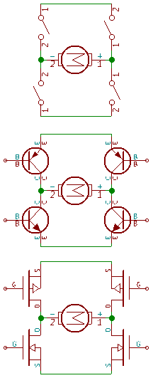
(a)Concept
(b)Bipolar implementation
(c)MOSfet implementation

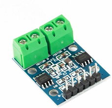
L9110 PCB

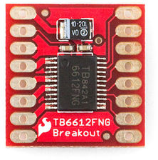
TB6612 PCB


DC motors typically use an H-bridge drive circuit. This allows forward and backward operation by reversing the polarity of the voltage applied to the motor.
For the small motors in small robots, there are two basic ways to implement an H-bridge circuit:
When used as switches these two types have significantly different electrical characteristics.
In the on state, a bipolar transistor switch operates in what's called “saturation mode”. When in saturation, there is a relatively fixed voltage drop across the transistor. I say “relatively”, because it does vary somewhat with current. The saturation voltage can be a few tenths of a volt, up to one volt or more for power transistors handling large currents.
MOS transistor switches behave much like a resistor - the voltage across the transistor is proportional to the current it's carrying. The effective resistance value depends on both the physical size of the transistor and the applied gate voltage.
So the bottom line is that a MOS-based H-bridge typically has less voltage drop across the switch itself than a comparable bipolar implementation. That means less heating of the switch, and less need for a heat sink. Also, for low battery voltages (say, 5 volts and below) the difference in voltage applied to the motor itself can make a difference in performance.
These are some chips commonly used in small motor driver boards.
| Chip | Input | Output | Voltage Drop |
|---|---|---|---|
| L9110 | 2.5-12V | 800mA | 2.85V@750mA,9V |
| HG7881 | 2.4-10V | 0.6-1A | 1.7V@800mA,6V |
| L298 | ≤46 | 2.0A | 2.55V@1A 3.7@2A |
| TB6612 | 2.5-13.5 | 1.0A | 0.5V@1A 0.15V@0.3A |
Some comments:
So as a selection guide: